442 Results
View Results:
Sort by:

The ASCE 7-22 Standard [1], Sect. 12.9.1.6 specifies when P-delta effects should be considered when running a modal response spectrum analysis for seismic design. In the NBC 2020 [2], Sent. 4.1.8.3.8.c gives only a short requirement that sway effects due to the interaction of gravity loads with the deformed structure should be considered. Therefore, there may be situations where second-order effects, also known as P-delta, must be considered when carrying out a seismic analysis.

Lateral-Torsional Buckling (LTB) is a phenomenon that occurs when a beam or structural member is subjected to bending and the compression flange is not sufficiently supported laterally. This leads to a combination of lateral displacement and twisting. It is a critical consideration in the design of structural elements, especially in slender beams and girders.

RWIND 2 and RFEM 6 can now be used to calculate wind loads from experimentally measured wind pressures on surfaces. Basically, two interpolation methods are available to distribute pressures measured in isolated points across the surfaces. The desired pressure distribution can be achieved using the appropriate method and parameter settings.

Using the Timber Design add-on, timber column design is possible according to the 2018 NDS standard ASD method. Accurately calculating timber member compressive capacity and adjustment factors is important for safety considerations and design. The following article will verify the maximum critical buckling strength calculated by the Timber Design add-on using step-by-step analytical equations as per the NDS 2018 standard including the compressive adjustment factors, adjusted compressive design value, and final design ratio.

In this article, you will learn how to model and design cable structures in RFEM 6 or RSTAB 9.

The data exchange between RFEM 6 and Allplan can be done using various file formats. This article describes the data exchange of a determined surface reinforcement using the ASF interface. This allows you to display the RFEM reinforcement values as level curves or colored reinforcement images in Allplan.

The three types of moment frames (Ordinary, Intermediate, Special) are available in the Steel Design add-on of RFEM 6. The seismic design result according to AISC 341-22 is categorized into two sections: member requirements and connection requirements.
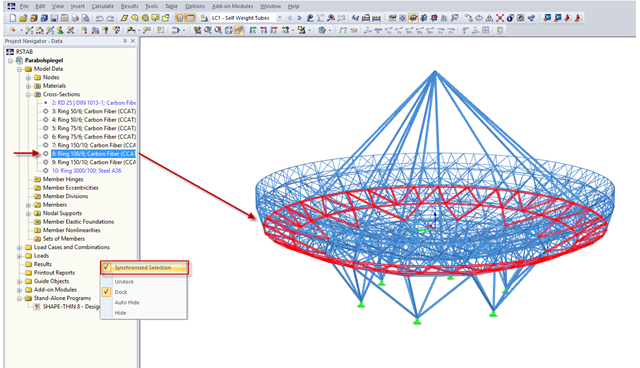
RFEM and RSTAB provide a wide range of selection options. Among other things, the selection using "Special Selection" or tables was mentioned.

When wind-induced surface pressures on a building are available, they can be applied on a structural model in RFEM 6, processed by RWIND 2, and used as wind loads for static analysis in RFEM 6.
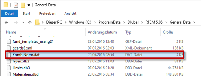
RFEM and RSTAB provide the option to create national annexes with user-defined partial safety factors and combination coefficients. They can also be transferred to other computers.

Moment frame design according to AISC 341-16 is now possible in the Steel Design add-on of RFEM 6. The seismic design result is categorized into two sections: member requirements and connection requirements. This article covers the required strength of the connection. An example comparison of the results between RFEM and the AISC Seismic Design Manual [2] is presented.
You can select an object in RFEM or RSTAB by simply clicking it. However, only the last object clicked will stay selected. In order to select several objects at a time, press the Control key while clicking. Since this procedure is not always possible, you can use the "Add to Selection" function in the toolbar or in the "Edit" → "Select" menu.
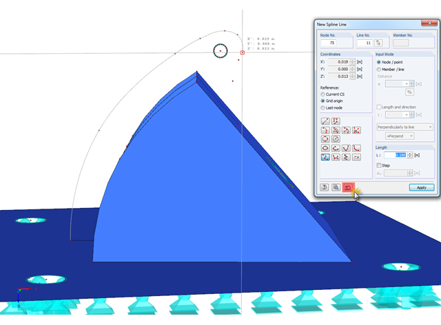
In RFEM, if you want to display a curved geometry (preferably in one continuous line), you can use splines or NURBS, for example. When modeling, you should pick the individual nodes one after another. If a mistake is made, you can go back using the special Undo function in the "New Spline Line" window. Thus, it is not necessary to enter the entire continuous line again.
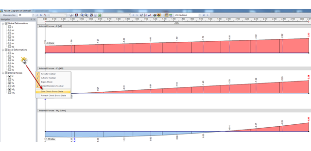
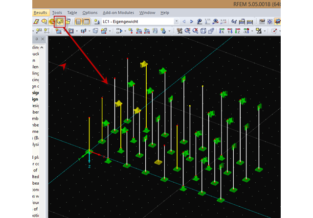
In RFEM and RSTAB, the check boxes for deformation in result diagrams are selected by default. To avoid creating a new user-defined result display every time, you can save the selection of check boxes displayed on the left.
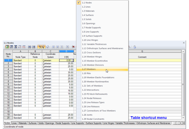
The geometry data of an RFEM model are currently managed in 29 tables, so not all of the tabs are displayed at once. To open a particular table, we recommend using the navigation menu that you can open by right-clicking on any tab. A shortcut menu appears, where you can quickly access the desired input table.

To evaluate whether it is also necessary to consider the second-order analysis in a dynamic calculation, the sensitivity coefficient of interstory drift θ is provided in EN 1998‑1, Sections 2.2.2 and 4.4.2.2. It can be calculated and analyzed using RFEM 6 and RSTAB 9.
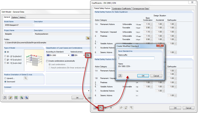
RFEM and RSTAB provide the option to create load and result combinations automatically according to the combination expressions defined in the standards. Partial safety factors and combination coefficients are specified in the standards or National Annexes. You can customize them as necessary and save them in a modified standard.

The three types of moment frames (Ordinary, Intermediate, Special) are available in the Steel Design add-on of RFEM 6. The seismic design result according to AISC 341-16 is categorized into two sections: member requirements and connection requirements.
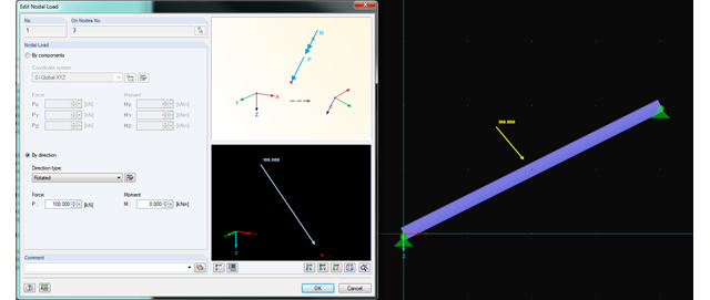
In RFEM and RSTAB, you can now rotate nodal loads or apply them on member axes. Thus, inclined members can also be loaded with nodal loads perpendicularly or along the member axis.

The new RF‑/DYNAM Pro - Natural Vibrations module has been available since RFEM version 5.04.xx and RSTAB version 8.04.xx were released. Masses can now be imported directly from load cases and load combinations.